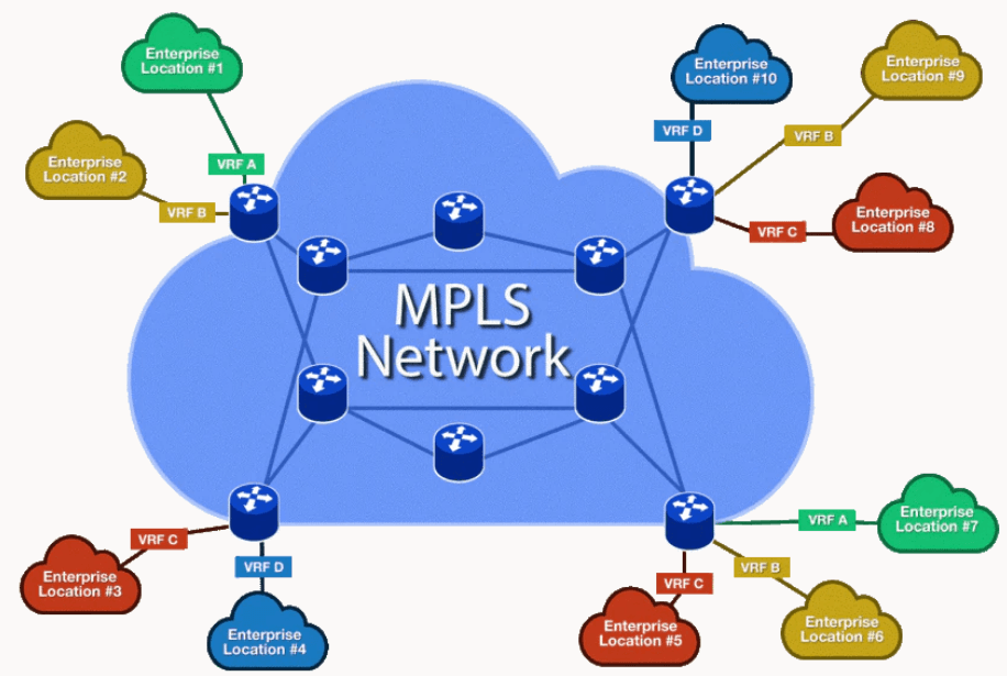
Multiprotocol Label Switching (MPLS) is a routing technique in telecommunications networks that directs data from one node to the next based on short path labels rather than long network addresses, thus avoiding complex lookups in a routing table and speeding traffic flows.
Simple MPLS step by step configuration.
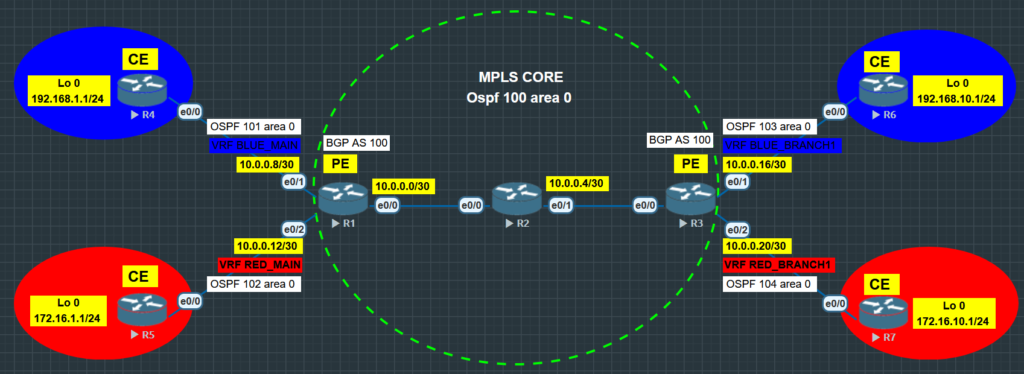
STEP 1 - IP addressing
Initial configuration.
Let’s create our topology first in Eve-ng software then
copy paste the initial configuration below to all routers.
| !R1 |
| en |
| conf t |
| int r e0/0-2 |
| bandwidth 100000 |
| no shut |
| ! |
| int lo 0 |
| ip add 1.1.1.1 255.255.255.255 |
| int e0/0 |
| ip add 10.0.0.1 255.255.255.252 |
| int e0/1 |
| ip add 10.0.0.9 255.255.255.252 |
| int e0/2 |
| ip add 10.0.0.13 255.255.255.252 |
| do wr |
| !################################### |
| !R2 |
| en |
| conf t |
| int r e0/0-1 |
| bandwidth 100000 |
| no shut |
| ! |
| int lo 0 |
| ip add 2.2.2.2 255.255.255.255 |
| int e0/0 |
| ip add 10.0.0.2 255.255.255.252 |
| int e0/1 |
| ip add 10.0.0.5 255.255.255.252 |
| do wr |
| !################################### |
| !R3 |
| en |
| conf t |
| int r e0/0-3 |
| bandwidth 100000 |
| no shut |
| ! |
| int lo 0 |
| ip add 3.3.3.3 255.255.255.255 |
| int e0/0 |
| ip add 10.0.0.6 255.255.255.252 |
| int e0/1 |
| ip add 10.0.0.17 255.255.255.252 |
| int e0/2 |
| ip add 10.0.0.21 255.255.255.252 |
| ! |
| do wr |
| !################################### |
| !R4 |
| en |
| conf t |
| int lo 0 |
| ip add 192.168.1.1 255.255.255.0 |
| int e0/0 |
| ip add 10.0.0.10 255.255.255.252 |
| bandwidth 100000 |
| no shut |
| do wr |
| !################################### |
| !R5 |
| en |
| conf t |
| int lo 0 |
| ip add 172.16.1.1 255.255.255.0 |
| int e0/0 |
| ip add 10.0.0.14 255.255.255.252 |
| bandwidth 100000 |
| no shut |
| do wr |
| !################################### |
| !R6 |
| en |
| conf t |
| int lo 0 |
| ip add 192.168.10.1 255.255.255.0 |
| int e0/0 |
| ip add 10.0.0.18 255.255.255.252 |
| bandwidth 100000 |
| no shut |
| do wr |
| !################################### |
| !R7 |
| en |
| conf t |
| int lo 0 |
| ip add 172.16.10.1 255.255.255.0 |
| int e0/0 |
| ip add 10.0.0.22 255.255.255.252 |
| bandwidth 100000 |
| no shut |
| do wr |
| !################################### |
STEP 2 - MPLS Core (LDP)
Configure OSPF protocol from R1 to R3. Enable LDP on all routers participating in the MPLS CORE.
Make sure to have full connectivity including the loopbacks IP address.
We can verify by pinging every router’s loopback IP address.
| !R1 |
| en |
| conf t |
| int r e0/0-2 |
| ip os net point-to-point |
| ! |
| router os 100 |
| router-id 1.1.1.1 |
| mpls ldp autoconfig |
| ! |
| int lo 0 |
| ip os 100 area 0 |
| int e0/0 |
| ip os 100 area 0 |
| do wr |
| !################################### |
| !R2 |
| en |
| conf t |
| int r e0/0-1 |
| ip os net point-to-point |
| ! |
| router os 100 |
| router-id 2.2.2.2 |
| mpls ldp autoconfig |
| ! |
| int lo 0 |
| ip os 100 area 0 |
| int r e0/0-1 |
| ip os 100 area 0 |
| do wr |
| !################################### |
| !R3 |
| en |
| conf t |
| int r e0/0-2 |
| ip os net point-to-point |
| ! |
| router os 100 |
| router-id 3.3.3.3 |
| mpls ldp autoconfig |
| ! |
| int lo 0 |
| ip os 100 area 0 |
| int r e0/0 |
| ip os 100 area 0 |
| do wr |
| !################################### |
Verify:
show mpls interface
show mpls ldp neighbour
show mpls ldp discovery
show mpls forwarding-table
One more verification to confirm LDP is running ok is to do a traceroute
between routers and verify if you get MPLS Labels show up in the trace.
STEP 3 - Multi Protocol BGP
Establish BGP vpnv4 address family between Provider Edge Routers. (R1 and R3.)
Vpnv4 address-family is well secured.
| !R1 |
| en |
| conf t |
| router bgp 100 |
| neighbor 3.3.3.3 remote-as 100 |
| neighbor 3.3.3.3 update-source lo0 |
| neighbor 3.3.3.3 ebgp-multihop 3 |
| ! |
| address-family vpnv4 |
| neighbor 3.3.3.3 activate |
| do wr |
| !################################### |
| !R3 |
| en |
| conf t |
| router bgp 100 |
| neighbor 1.1.1.1 remote-as 100 |
| neighbor 1.1.1.1 update-source lo0 |
| neighbor 1.1.1.1 ebgp-multihop 3 |
| ! |
| address-family vpnv4 |
| neighbor 1.1.1.1 activate |
| do wr |
| !################################### |
Verify:
Show ip bgp vpnv4 all summary
Step 4 - Virtual Routing Protocols (VRF)
VRF allows multiple instances of routing tables to co-exist in a router and work together without interfering with each other. Each VRF routing instance lives in different dimension.
| !R1 |
| en |
| conf t |
| !Create VRF BLUE |
| ip vrf BLUE_MAIN |
| rd 100:8 |
| !100 is the BGP AS number and 8 is Network IP Address |
| !Identify the export and import of Route Distinguisher’s |
| route-target export 100:8 |
| route-target import 100:16 |
| ! |
| !Apply vrf BLUE_MAIN in an interface that is connected to BLUE router |
| int e0/1 |
| ip vrf forwarding BLUE_MAIN |
| ip add 10.0.0.9 255.255.255.252 |
| ! |
| !Create VRF RED |
| ip vrf RED_MAIN |
| rd 100:12 |
| route-target export 100:12 |
| route-target import 100:20 |
| ! |
| int e0/2 |
| ip vrf forwarding RED_MAIN |
| ip add 10.0.0.13 255.255.255.252 |
| do wr |
| !############################################################### |
| !R3 |
| en |
| conf t |
| !Create VRF BLUE |
| ip vrf BLUE_BRANCH1 |
| rd 100:16 |
| route-target export 100:16 |
| route-target import 100:8 |
| ! |
| int e0/1 |
| ip vrf forwarding BLUE_BRANCH1 |
| ip add 10.0.0.17 255.255.255.252 |
| ! |
| !Create VRF RED |
| ip vrf RED_BRANCH1 |
| rd 100:20 |
| route-target export 100:20 |
| route-target import 100:12 |
| ! |
| int e0/2 |
| ip vrf forwarding RED_BRANCH1 |
| ip add 10.0.0.21 255.255.255.252 |
| do wr |
| ! |
Verify:
show ip route vrf
show ip route BLUE_MAIN
show ip route RED_MAIN
Step 5 - PE and CE neighbor formation
Establish a neighborship between Provider Edge and Customer Edge Router.
We can use either BGP, RIP, EIGRP(Named), or OSPF.
| !R1 |
| !R1 peering to R4 |
| en |
| conf t |
| router os 101 vrf BLUE_MAIN |
| router-id 1.1.1.8 |
| net 10.0.0.8 0.0.0.3 area 0 |
| ! |
| !R1 peering to R5 |
| router os 102 vrf RED_MAIN |
| router-id 1.1.1.12 |
| net 10.0.0.12 0.0.0.3 area 0 |
| do wr |
| !################################### |
| !R4 |
| !R4 peering to R1 |
| en |
| conf t |
| int e0/0 |
| ip os net point-to-point |
| ! |
| router os 101 |
| router-id 4.4.4.4 |
| net 192.168.1.0 0.0.0.255 area 0 |
| net 10.0.0.8 0.0.0.3 area 0 |
| do wr |
| !################################### |
| ! |
| !Before we continue We need to make sure that everything is configured correctly. |
| !Verify first |
| !On R1 do “show ip route vrf BLUE_MAIN |
| !We should see and can ping the network 192.168.1.0/24 fron R1 |
| !On R1 do “ping vrf BLUE_MAIN 192.168.1.1” |
| ! |
| !################################### |
| !R5 |
| !R5 peering to R1 |
| en |
| conf t |
| int e0/0 |
| ip os net point-to-point |
| ! |
| router os 102 |
| router-id 5.5.5.5 |
| net 172.16.1.0 0.0.0.255 area 0 |
| net 10.0.0.12 0.0.0.3 area 0 |
| do wr |
| !################################### |
| !################################### |
| !################################### |
| !################################### |
| !R3 |
| !R3 peering to R6 |
| en |
| conf t |
| router os 103 vrf BLUE_BRANCH1 |
| router-id 3.3.3.16 |
| net 10.0.0.16 0.0.0.3 area 0 |
| ! |
| !R3 peering to R7 |
| router os 104 vrf RED_BRANCH1 |
| router-id 3.3.3.20 |
| net 10.0.0.20 0.0.0.3 area 0 |
| do wr |
| !################################### |
| !R6 |
| !R6 peering to R3 |
| en |
| conf t |
| int e0/0 |
| ip os net point-to-point |
| ! |
| router os 101 |
| router-id 6.6.6.6 |
| net 192.168.10.0 0.0.0.255 area 0 |
| net 10.0.0.16 0.0.0.3 area 0 |
| do wr |
| !################################### |
| !R7 |
| !R7 peering to R3 |
| en |
| conf t |
| int e0/0 |
| ip os net point-to-point |
| ! |
| router os 102 |
| router-id 7.7.7.7 |
| net 172.16.10.0 0.0.0.255 area 0 |
| net 10.0.0.20 0.0.0.3 area 0 |
| do wr |
| !################################### |
Step 6 - Mutual Redistribution
Redistributes between two routing protocols in both directions. OSPF to BGP
and BGP to OSPF
| !Mutal Redistribution for VRF BLUE |
| !R1 |
| en |
| conf t |
| !OSPF to BGP |
| router bgp 100 |
| address-family ipv4 vrf BLUE_MAIN |
| redistribute ospf 101 |
| ! |
| !Verify first |
| !sh ip bgp vpnv4 all summary |
| !We should see value or number of advertised network under prefix received |
| !sh ip route vrf BLUE_BRANCH1 |
| !We now have the 192.168.1.0/24 network advertised as BGP. |
| ! |
| !BGP to OSPF |
| router os 101 |
| redistribute bgp 100 subnets metric-type 1 |
| do wr |
| ! |
| !Verify |
| !sh run | sec redistribute |
| ! |
| ! |
| ! |
| !R3 |
| en |
| conf t |
| !OSPF to BGP |
| router bgp 100 |
| address-family ipv4 vrf BLUE_BRANCH1 |
| redistribute ospf 103 |
| ! |
| !BGP to OSPF |
| router os 103 |
| redistribute bgp 100 subnets metric-type 1 |
| do wr |
| ! |
| !Verify |
| !On R6 we should ping the loopback of R4 |
| !ping 192.168.1.1 source Lo 0 |
| !Now lets verify if MPLS network is working fine |
| !On R6 traceroute 192.168.1.1 source lo0 |
| !We should see an MPLS labels on the trace |
| ! |
| !############################################ |
| !############################################ |
| !############################################ |
| !Mutal Redistribution for VRF RED |
| !R1 |
| en |
| conf t |
| !OSPF to BGP |
| router bgp 100 |
| address-family ipv4 vrf RED_MAIN |
| redistribute ospf 102 |
| ! |
| !BGP to OSPF |
| router os 102 |
| redistribute bgp 100 subnets metric-type 1 |
| do wr |
| ! |
| !R3 |
| en |
| conf t |
| !OSPF to BGP |
| router bgp 100 |
| address-family ipv4 vrf RED_BRANCH1 |
| redistribute ospf 104 |
| ! |
| !BGP to OSPF |
| router os 104 |
| redistribute bgp 100 subnets metric-type 1 |
| do wr |
| !############################################ |
| !############################################ |
Verify:
On R1 do traceroute to R6 loopback IP address.
We should see an MPLS labels on the trace