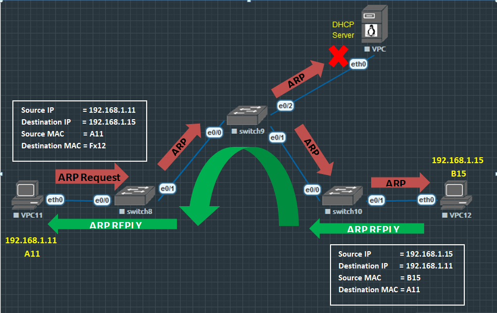
Hold a map called Mac-Adress Table. Unlike HUB, switch forward its frame to a specific destination only.
How does the switch works? Initially, switches broadcast an ARP request to acquire the MAC address of the destination device. (Let say that DHCP DORA had already established) . Records can be seen in the ARP table and MAC-address table.
Access port = Port of the switch connected to End Devices. Trunk port = Port connected to another switch. Member of all Vlan’s. Encapsulation = 802.1q
Verify commands: Show mac-address-table Show int f0/1 switchport
Switch Best Practice:
1.) Turn off unused port. Switch(config)#int r e0/2-3, e1/0-3 Switch(config-if-range)#shutdown
2.) Manually configure (hard coded) Trunk interface or Access interface.
Switch(config)#int r e0/0-1 Switch(config-if-range)#sw trunk encapsulation dot1q Switch(config-if-range)#sw mode trunk Switch(config-if-range)#int r e0/2-3, e1/0-3 Switch(config-if-range)#sw mo access
3.) On Access Port Configure the folowing commands: nonegotiate STP portfast STP bpduguard sw port security uplinkfast, backbonefast rootguard loopguard
Verify: show run int e0/2 Show port-security Show port-security int e0/2
Vlan = Logically divide networks into different broadcast domains. Save in flash memory. InterVlan = Multiple Vlans interconnecting to each other with the use of Layer3 switch or a Router.
Spanning Tree
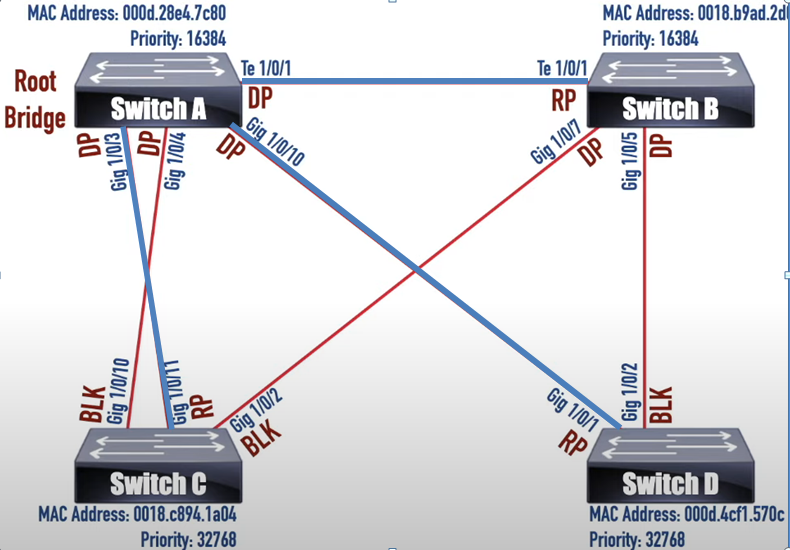
Prevent loop in a redundant network design. STP will only choose the best path going to Root bridge. As shown below switch B, C, and D best path are highlighted in blue.
Best Practice to manually configure the Root Bridge.
Assigning STP Port Roles
1. All Rootbridge ports are Designated Ports. 2. Determine Root Port. All lowest STP costs going to Rootbridge are Root port. 3. Rootport opposite side is always Designated port. 4. Blocking port opposite side is always Designated port. 5. Tie Breaker The lowest Mac Address will be the Designated port
Default STP Port Cost
10 Mbps = 100 100 Mbps = 19 1 Gbps = 4 Higher than 10 Gbps Long Path Cost method is used.
Note: We can change the port priority on an Interface STP Modes = RSTP/ Rapid PVST / MST
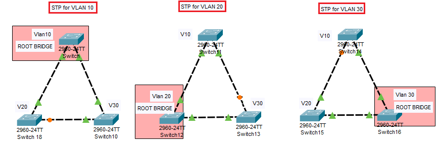
Rapid Per Vlan Spanning Tree
Configuration: Spanning tree mode Rapid PVST Spanning tree vlan <number> root <primary/secondary>
MST/Mstp (Multiple Spanning Tree) 802.1s
We can group VLAN’s and put them together in an INSTANCE
Mst0 = all VLAN’s not included in configuration
Commands for getting the Base MAC Address of a switch sh tech | i Amd sh spanning tree sh spanning tree mst sh ver show interfaces | i (.* line protocol is )|(.* address is)
Sample Configuration:
###Do this on primary switch for MST instance 1 ### Spanning-tree mode mst Spanning-tree mst configuration Name MYMST Revision 100 Instance 1 vlan 10,20 Instance 2 vlan 30-40 ! Spanning-tree mst 1 root primary Spanning-tree mst 2 root secondary (best practise to manually configure the priority for secondary rootbridge) ! ###Do this on primary switches for MST instance 2 ### Spanning-tree mode mst Spanning-tree mst configuration Name MYMST Revision 100 Instance 1 vlan 10,20 Instance 2 vlan 30-40 ! Spanning-tree mst 1 root secondary Spanning-tree mst 2 root primary
Verify: show spanning tree mst configuration Show spanning tree root Show spanning tree mst
VTP (Virtual Trunking Protocol)
VLAN propagation. Configure VLAN in Server Switch then it will propagate to all Client Switches.
Vtp mode <Server/Client/Transparent>
VTP Domain and Password
Must be a Trunk link
VTP Version 3
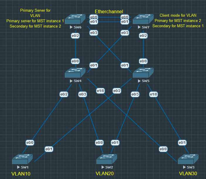
1.Has Primary Server for VLANs. This primary server is the only switch that can create/delete/modify VLAN’s 2.Has Primary Server for MST. This primary server is the only switch that can create/delete/modify MST Instances. 3.Prevent accidentally overwriting of VLAN database.
Best practice to avoid accidentally overwriting Vlan database 1.For newly acquired switch set it first to transparent mode so that the revision number will reset back to zero. 2.Use VTP version 3
Sample Configuration:
#Configure this on all switches## Switch(config)#Vtp domain DOMAIN Switch(config)#Vtp version 3 Switch(config)#Vtp password PASS hidden Switch(config)#Vtp pruning Switch(config)#spanning-tree mode mst
! ! #### Configure this on desired switch needed to be PRIMARY SERVER for VLAN and MST (Switch6). #### Configure on Sharp (#) ! #Vtp primary vlan (must be in server mode first) #Vtp primary mst (must be in server mode first) ! #Incase of failure turn VTP VLAN/MST mode to Server first. Switch(config)#vtp mode server mst ! ! #Configure this on all switches that need to in Client mode for VLAN and MST Switch(config)#vtp mode client vlan Switch(config)#vtp mode client mst ! verify: show vtp status
We can now create VLANS on SW6 (Primary Server for Vlan and MST)
en conf t vlan 10 name V10 vlan 11 vlan 20 vlan 21